|
|||
|
Part I Designing Device Drivers for the Solaris Platform 1. Overview of Solaris Device Drivers 2. Solaris Kernel and Device Tree 5. Managing Events and Queueing Tasks Data Structures Required for Drivers 7. Device Access: Programmed I/O 10. Mapping Device and Kernel Memory 14. Layered Driver Interface (LDI) Part II Designing Specific Kinds of Device Drivers 15. Drivers for Character Devices 18. SCSI Host Bus Adapter Drivers 19. Drivers for Network Devices Part III Building a Device Driver 21. Compiling, Loading, Packaging, and Testing Drivers 22. Debugging, Testing, and Tuning Device Drivers 23. Recommended Coding Practices B. Summary of Solaris DDI/DKI Services C. Making a Device Driver 64-Bit Ready |
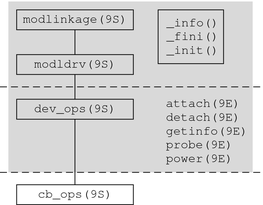
Driver Loading and UnloadingThe system loads driver binary modules from the drv subdirectory of the kernel module directory for autoconfiguration. See Copying the Driver to a Module Directory. After a module is read into memory with all symbols resolved, the system calls the _init(9E) entry point for that module. The _init() function calls mod_install(9F), which actually loads the module. Note - During the call to mod_install(), other threads are able to call attach(9E) as soon as mod_install() is called. From a programming standpoint, all _init() initialization must occur before mod_install() is called. If mod_install() fails (that is a nonzero value is returned), then the initialization must be backed out. Upon successful completion of _init(), the driver is properly registered with the system. At this point, the driver is not actively managing any device. Device management happens as part of device configuration. The system unloads driver binary modules either to conserve system memory or at the explicit request of a user. Before deleting the driver code and data from memory, the _fini(9E) entry point of the driver is invoked. The driver is unloaded, if and only if _fini() returns success. The following figure provides a structural overview of a device driver. The shaded area highlights the driver data structures and entry points. The upper half of the shaded area contains data structures and entry points that support driver loading and unloading. The lower half is concerned with driver configuration. Figure 6-1 Module Loading and Autoconfiguration Entry Points
|
||
|